Use NOR gates to implement a logic function
NOR Logic
A NOR gate can function as either a NOR or a negative-AND, as shown by DeMorgan’s theorem.

 |
| FIGURE 1 NOR logic for X 5 (A 1 B)(C 1 D). |
Consider the NOR logic in Figure 1. The output expression is developed as follows:
As you can see in Figure 1, the output expression (A + B)(C + D) consists of two OR terms ANDed together. This shows that gates G2 and G3 act as OR gates and gate G1 acts as an AND gate, as illustrated in Figure 2(a). This circuit is redrawn in part (b) with a negative-AND symbol for gate G1.
 |
| FIGURE 2 |
NOR Logic Diagram Using Dual Symbols
As with NAND logic, the purpose for using the dual symbols is to make the logic diagram easier to read and analyze, as illustrated in the NOR logic circuit in Figure 3. When the circuit in part (a) is redrawn with dual symbols in part (b), notice that all output-to-input
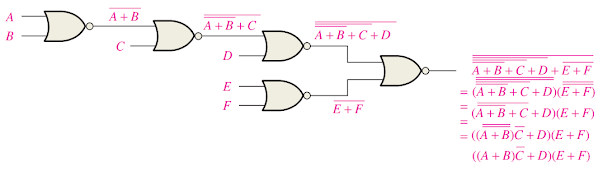 |
| FIGURE 3(a) Final output expression is obtained after several Boolean steps
|
 |
| FIGURE 3(b) Output expression can be obtained directly from the function of each gate symbol in the diagram. |
connections between gates are bubble-to-bubble or nonbubble-to-nonbubble. Again, you can see that the shape of each gate symbol indicates the type of term (AND or OR) that it produces in the output expression, thus making the output expression easier to determine and the logic diagram easier to analyze.
EXAMPLE 1
Using appropriate dual symbols, redraw the logic diagram and develop the output expression for the circuit

Solution
Redraw the logic diagram with the equivalent negative-AND symbols as shown:

Post a Comment
0 Comments