Use full-adders to implement a parallel binary adder

As you learned, a single full-adder is capable of adding two 1-bit numbers and an input carry. To add binary numbers with more than one bit, you must use additional full-adders. When one binary number is added to another, each column generates a sum bit and a 1 or 0 carry bit to the next column to the left, as illustrated here with 2-bit numbers.

To add two binary numbers, a full-adder (FA) is required for each bit in the numbers. So for 2-bit numbers, two adders are needed; for 4-bit numbers, four adders are used; and so on. The carry output of each adder is connected to the carry input of the next higher-order adder, as shown in Figure 1 for a 2-bit adder.

|
|
FIGURE 1: Block diagram of a basic 2-bit parallel adder using two
full-adders.
|
Notice that either a half-adder can be used for the least significant position or the carry input of a full-adder can be made 0 (grounded) because there is no carry input to the least significant bit position.
In Figure 1 the least significant bits (LSB) of the two numbers are represented by A1 and B1 . The next higher-order bits are represented by A2 and B2 . The three sum bits are Σ1 , Σ2 , and Σ3 . Notice that the output carry from the left-most full-adder becomes the most significant bit (MSB) in the sum, Σ3.
EXAMPLE 1:
Determine the sum generated by the 3-bit parallel adder in Figure and show the intermediate carries when the binary numbers 101 and 011 are being added.

Solution:
The LSBs of the two numbers are added in the right-most full-adder. The sum bits and the intermediate carries are indicated in blue:

Four-Bit Parallel Adders
A group of four bits is called a nibble. A basic 4-bit parallel adder is implemented with four full-adder stages as shown in Figure 2 et 3. Again, the LSBs (A1 and B1) in each number being added go into the right-most full-adder; the higher-order bits are applied as shown to the successively higher-order adders, with the MSBs (A4 and B4) in each number being applied to the left-most full-adder. The carry output of each adder is connected to the carry input of the next higher-order adder as indicated. These are called internal carries.
 |
| FIGURE 2: A 4-bit parallel adder, Block diagram |
 |
| FIGURE 3:
A 4-bit parallel adder, Logic symbol |
Adder Expansion
The 4-bit parallel adder can be expanded to handle the addition of two 8-bit numbers by using two 4-bit adders. The carry input of the low-order adder (C0) is connected to ground because there is no carry into the least significant bit position, and the carry output of the low-order adder is connected to the carry input of the high-order adder, as shown in Figure 4. This process is known as cascading. Notice that, in this case, the output carry is designated C8 because it is generated from the eighth bit position. The low-order adder is the one that adds the lower or less significant four bits in the numbers, and the high-order adder is the one that adds the higher or more significant four bits in the 8-bit numbers. Similarly, four 4-bit adders can be cascaded to handle two 16-bit numbers.
 |
| FIGURE 4: Cascading of two 4-bit adders to form an 8-bit adder |
IMPLEMENTATION: 4-BIT PARALLEL ADDER

Show how two 74HC283 adders can be connected to form an 8-bit parallel adder. Show output bits for the following 8-bit input numbers:
Solution:
Two 74HC283 4-bit parallel adders are used to implement the 8-bit adder. The only connection between the two 74HC283s is the carry output (pin 9) of the low-order adder to the carry input (pin 7) of the high-order adder
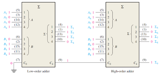
Pin 7 of the low-order adder is grounded (no carry input). The sum of the two 8-bit numbers is:
Post a Comment
0 Comments